Overview

This blog is intended to document the build of my Gardner Douglas Mk4 Cobra; partly as IVA evidence, bit primarily to help others learn from my mistakes and/or successes.

I will endeavour to post as often as possible, with a view to entering a single post for a particular element of the build process, however inevitably some things may not be completed in one go. All posts will be tagged so it should be easy enough to find the information you seek.

Please subscribe to receive emailed updates and feel free to post any comments or questions which I will make my best efforts to respond to.

Thursday 10 March 2016

Flash lines part 1

I managed to grab a couple of hours to have a go at some flash lines tonight. I haven't been looking forward to this at all, but I can't put it off forever. Other people have done an area from start to finish but I've decided to do the whole car 1 stage at a time.

I started by masking off about 5mm either side of the flash lines all round and then carefully 'shaved' the worst of it all off by drawing a Stanley blade backwards at right angles to the flash line. This gets all but the thickness of the tape off.

I removed all the tape and started with the rear offside quarter panel with some P400 wet & dry (I used 3M paper as I've heard that quality and consistency was far superior to other brands) on a rubber sanding block and plenty of water from a spray bottle. I sanded in the direction of the line and was pleasantly surprised to see it come up quite well fairly easily. The rubber block works well over larger flat or slightly convex areas, but I used a small piece of closed cell foam to get in to the tighter corners and around the radius of the cockpit.

Although I can see that this will take some time, I'm more at ease than I was with the process and the results. I'm still not sure about the engine bay seam though, may even fill it and paint it black.

Near side rear quarter panel as it was out of the mould

Removing most of the flash line from offside quarter panel with Stanley blade 

Offside quarter panel after Stanley blade

I started with the rear light panel as this will mostly be covered so mattered less if I cocked it up! 

Nearside quarter panel after Stanley blade

Offside quarter panel after P400 wet & dry
Dash return after P400 wet & dry 

Wednesday 9 March 2016

Gas struts part 2

Boot
I though the boot would be as simple as the bonnet, how wrong was I! The body in general is much weaker than at the front and there is a much smaller return to bolt to. The rear struts are also from WDS but are 6mm diameter, 200mm stroke and 450mm length (502mm with the ball joints).

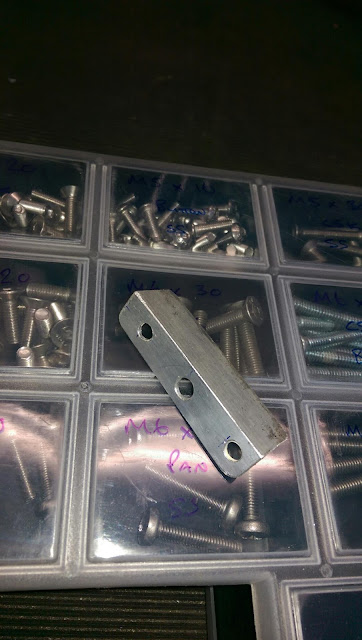
I first started off making an aluminium support bracket 60mm long but this proved to not spread the load enough so I made a longer one. With an 'L' section strengthener, the rain gutter around the boot opening reduces the 20mm lip even more so there is only just enough left to get a nut on the back.

The strengthener was bolted to the lip and the lower ball attached. The upper mount was much the same as the bonnet but the brackets had to be filed and bent to match the curve of the boot lid. The same was repeated for the othet side and the pressures adjusted, although I'm still not 100% happy with how it's turned out so may revisit this at a later date.

Strut offered up and mounting points marked

Marks transferred to outside to check clearance

Bracket held in place for drilling support holes

This bracket proved not to be long enough so a longer one was made

Modified angle bracket to take in to account tbe curvature of the boot lid
I used a similar method to transfer the lines across as I did with the bonnet

Friday 4 March 2016

Gas struts part 1

Hi I'm not keen on the agricultural operation and look of the GD supplied boot and bonnet stays so I've decided to go for gas struts.

I have used Dales blog as a basis although I got my struts from WDS Ltd, SDS did do stainless ones but they were twice the price.

Bonnet
I decided to use slightly longer struts than the GD stay, this will provide a bit more leverage hence a lower force is required which will hopefully alleviate the concerns of distortion to the bonnet. Atleast that's the theory!

I ordered adjustable struts with ball end fittings (model 850-0819250) which are about 600mm overall length with a 250mm stroke, the full spec can be seen here. I also ordered some 90 degree brackets with integral ball fittings for the top ends.

I started by propping the bonnet up so that the hinges were a few millimetres from touching the body, I then offered up an extended gas strut so it was just off vertical and marked the mounting points. I  now had a mark on the underside of the bonnet which was extended around to the top of the bonnet and another on the inner return of the engine which I transferred out to the wing.

Now with the bonnet shut I could transfer these line across and measure between them. As long as this measurement is more than the compressed length of the strut then everything will close fine.

Using some 3mm aluminium angle I created a strengthening plate to sit behind the return edge. Due to the radius of the return this bracket wouldn't sit flush against both the vertical and horizontal edges so I made some spacers too.

With this clamped in place I marked and drilled the pilot holes, then removed and opened all the holes out. Most are 6mm but for the ball end, I had to thin the GRP to recess it slightly as the thread wasn't long enough. This all then bolts in place and the strut can be connected and with the stainless 'L'  bracket connected to the other end the holes can be marked and drill on the bonnet rib. I used 2 M4 rivnuts here.

To ensure that the opposite side was mounted in the same place I had to transfer the mounting point centres to the other side, which is easier said than done due to there being nothing to easily measure from. My method was to tape a bit of string and the known point on the completed side then pull it taught across the bonnet. I then measured between the front of the bonnet and the string along the stripes each side then compared the two. I then adjusted, measured and compared until they matched then marked the othet side.

With the mounting points transferred across I installed the second strut using the same method as the first. Gas was released in 1 second squirts from each strut in stages so they were always equal, until they had enough force to keep the bonnet open without the bodywork flexing when trying to close.


Marking the lower mount (furthest point), the compressed strut length (middle point) and thr the actual closed position made sure nothing would foul. 

Strengthening bracket and spacers

Centre line of upper mount transferred to top of bonnet

Lower mounting point 

One down, one to go

Here you can see that the strut is angled, I changed the upper ball mount to straighten it

Transferring lines from one side to the other

All done 

Upper brackets changed from internal ball to external ball, straightening up the strut nicely. 

Thursday 3 March 2016

Fitting the bonnet

The bonnet fitment is much the same as the boot lid (see previous post), only slight easier as it can rest in place and you can do everything from below.

I did temporarily fit the 3 sealing strips around the engine bay return to get the right height. I added a washer to shim the whole bonnet right a bit as I did with the boot.

This is what the panel edges look like prior to filing... 

.... and after filing

Sealing strip temporarily fitted to help with setting the height

Fitting the boot lid

The first thing I did with the boot lid was to file down the edges to get the worst of flash line off, the edges will need gel coating, sanding and polishing but that's for another day. I did slip a couple of times and scratch the gel, hopefully these will polish out!

I then cleaned out the 8 hinge mounting holes in the boot lid with an M8 tap as also the 2 pivot holes on the underside of the boot ceiling with an M10 tap. I also had to remove a bit of excess fibreglass around these with a file.

The wire for the number plate light is already installed between the skins of the boot and a hole is already made in the right hand hinge mounting which I opened up a bit to be able to hook the cable with some bent welding wire and grab it with some needle nose pliers. This was also repeated at the other end where the light fits.

I have used the billet alloy hinges and they are a thing of beauty. With these there are 2 angle brackets which were bolted to the boot lid with 8 button head bolts, the hinges then bolt to these with an M8 and M6 button head bolts which are used for height adjustment later.

The fixing pack comes with the same brass bushes as provided with the standard hinges but these need cutting down about 10mm to fit the billet hinges.  I put the bush through the hinge, marked with a fine point permanent pen and cut just outside of this line. This leaves the bush slightly proud of the hinge.

With the boot and hinges assembled, I then offered it up to the hinge mounting points within the boot space (it's easier with a second pair of hands!). The bushes should be inserted from inside to out so they are between the hinge and mounting hole, then just screw in the M10 bolts.

The hinges can then be adjusted for height by loosening the bolt that goes through the banana slot slightly until you get the desired height and shut line. My lid was sitting slightly to the left so I inserted a washer between the right hand bush and body which brought it more central.

I also fitted the carbon effect number plate light but it looks a bit tacky next to the real carbon stripes. I have a friend who makes composites for F1 who is going to make me a proper carbon cover for the lamp.

Number plate light cable pulled through rigjt hand hinge mount

Billet alloy hinges fitted, lovely. 

Brass bush marked ready for trimming. 

Brass bush, before & after

Brass bush protruding about 0.5mm

Spacer washer installed. 

All done

Faux carbon number plate light needs changing 

Fitting the doors

There are 4 captive threads on each side behind the front edge of the door opening for the hinge mounts. These holes were treated to a clean out, I couldn't get a tap in there so used an M6 bolt with a slot cut down the middle.

I then bolted the hinge plates on but didn't tighten fully yet. The top bolt on each side is a real pain to get at but persistence paid off in the end. There are pre-marked rectangles on the front of the door opening, these were drilled and opened out with a file. Be careful not to open these too much as they stop the front of the door striking the body.

Although the 4 hinge arms all look identical, they are marked LT (left top), LB (left bottom) etc so I fitted them in those positions. My fitting pack came with pins rather than bolts that the manual refers to, these just slot in from the top with a washer on each end and a spring pin in the bottom.

The door edges were treated to the same file action as the boit and bonnet, taking particular care across the top inside edge as this will ve visible.

I then drilled out the pre-marked areas for the door latches, I drilled them small and then adjusted with a file until the correct size. I also cut out a section where the door handle mounts, this was easier than just drilling 3 holes and will be covered up with the door card anyway.

Four holes were marked on each door for the hinges but I found these to be way out when offering the door up. I taped over them and remarked through the hinges whilst holding the door in situ, then drilled these out to 13mm initially although these needed adjusting to get the shut lines right.

You can now slide the intrusion bar in to the door, along with the remote door release mechanism. The door release arm connects to the latch with an M6 button head and nyloc nut, I didn't tighten this fully and put a bit if grease on the joint as this will move. The intrusion beam can now be extended and the latch bolted to it through the door skin. The remote release bolts to the intrusion beam tabs with M6 cap heads. Screw the striker pin in to the captive thread on the rear door return.

The door assembly can now be offered up to the body and the hinges bolted through the door skin in to the intrusion bar. I had to open these holes up in the skin to allow for more wiggle room so therre was a bit of door on, door off, door back on action to get it right.

The same was done for the opposite door, both will have to come back off for gel repairs and polishing.

Hinge plate fitted to 'A Pillar'.   Slotted bolt holes allow for in/out adjustment

Pre-marked holes for door catches

Door catch connected to remote link

Remote linkage fitted to intrusion bar

Assembled and hung

Not too shabby although my mate reckons it looks too orange with the doors on! Bit late for that.